ESP32s for Block Detection and Point Control Using ESPHome
I've been working on updating my control system for my points and block detection this week. My control system is based on ESP32 micro controllers using ESPHome. This design has evolved over time, and I'd thought I'd share the process of updating a board.
What is ESPHome?
ESPHome is an open-source framework that allows you to create custom firmware for ESP8266 and ESP32-based devices. ESP8266 and ESP32 are popular Wi-Fi and Bluetooth-enabled microcontrollers commonly used in IoT (Internet of Things) projects.
ESPHome provides a simple yet powerful way to program and configure these devices without writing any code, making it accessible to both beginners and experienced developers. It is designed to work with Home Assistant, a popular open-source home automation platform, to integrate your ESP8266 and ESP32 devices into a larger home automation ecosystem.
This platform is great for model railroading as it takes away some of the more laborious tasks in writing code for arduino-like devices.
System Overview
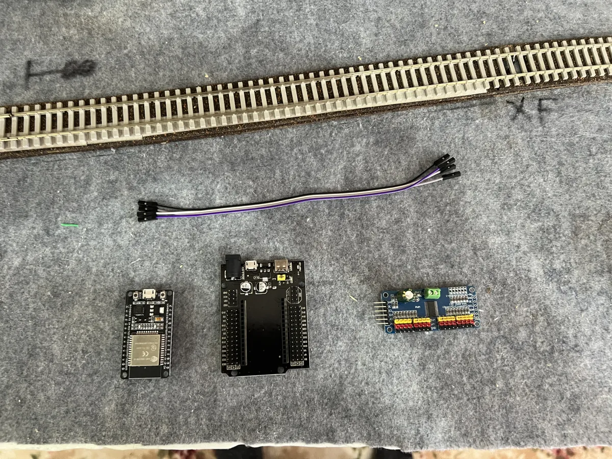
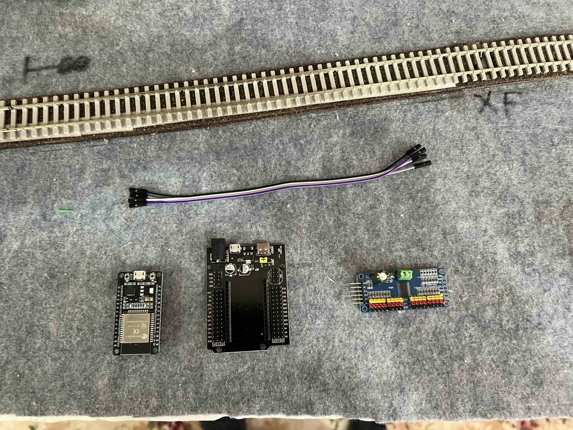
Each interlocking location on the layout has its own ESP32 board. These boards can support several digital or analog inputs as well as outputs. I use a PCA9685 board to control the servos, which allows me to keep them on a separate power supply. Previously I've powered the servos using the same supply as the ESPs, but I find anything greater than 3 servos on a board causes all sorts of issues.
Realistically you could run several locations on the layout using a single board, however they aren't that expensive. Each board/cable costs around $8. I make my detector boards for about the same price, so its quite affordable.
The boards are configured in ESPHome using YAML files. Each board is bootstrapped manually by flashing over a USB on a PC, however subsequent updates can be done over Wifi. One of the best features of ESPHome!
Out With The Old, In With The New
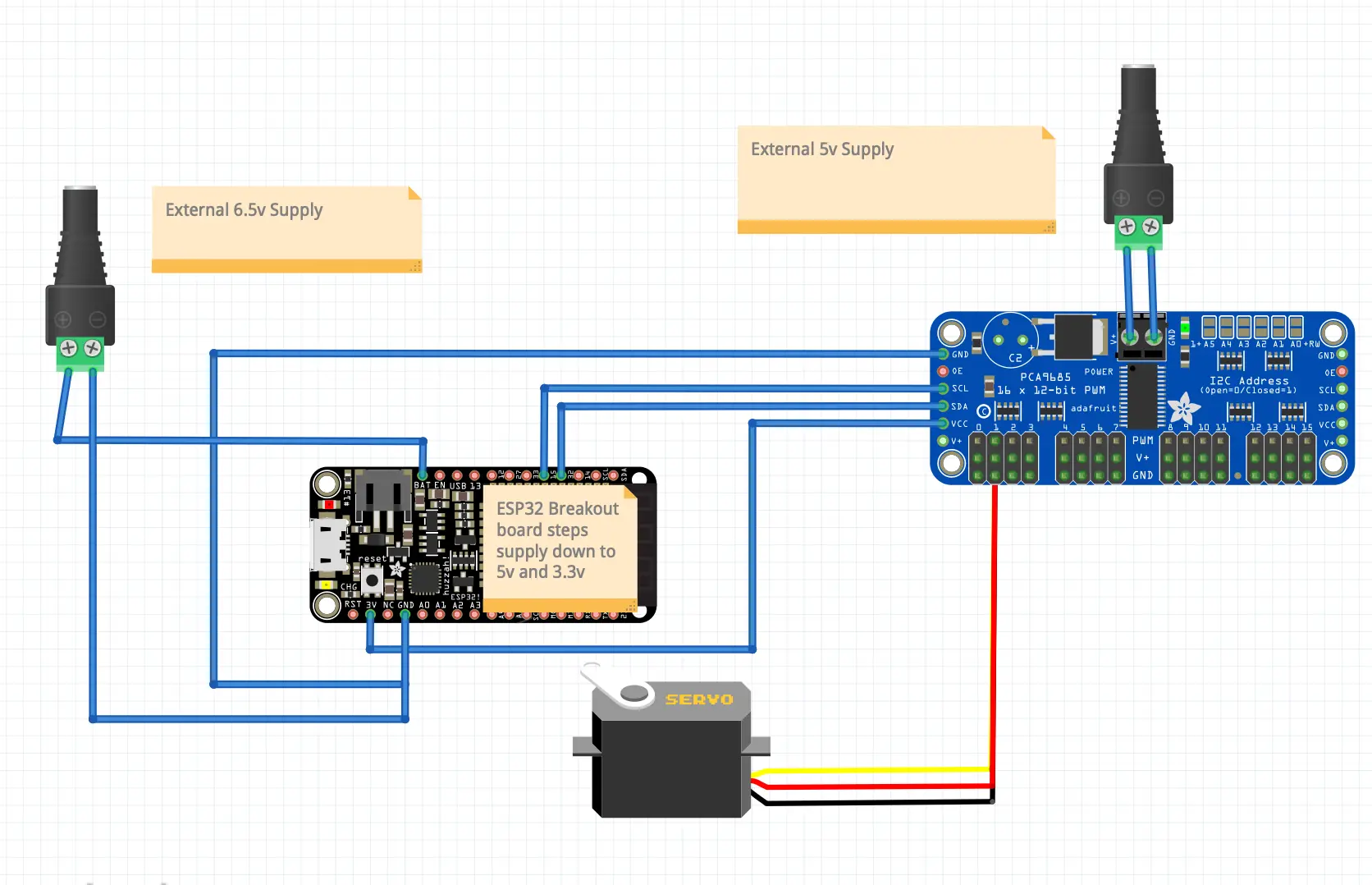
I'm replacing all of my old boards and moving to the design in the diagram above. I could use the existing boards, but I've replaced them for a few reasons:
- Cheaper
- Have a 5v or 3.3v bus available, configured using a jumper. They also have additional pins for both 5v and 3.3v
- Don't need to modify these boards, as I did to the old ones
- My OCD
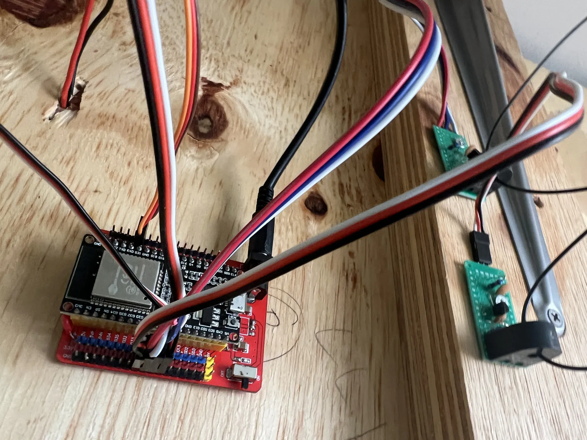
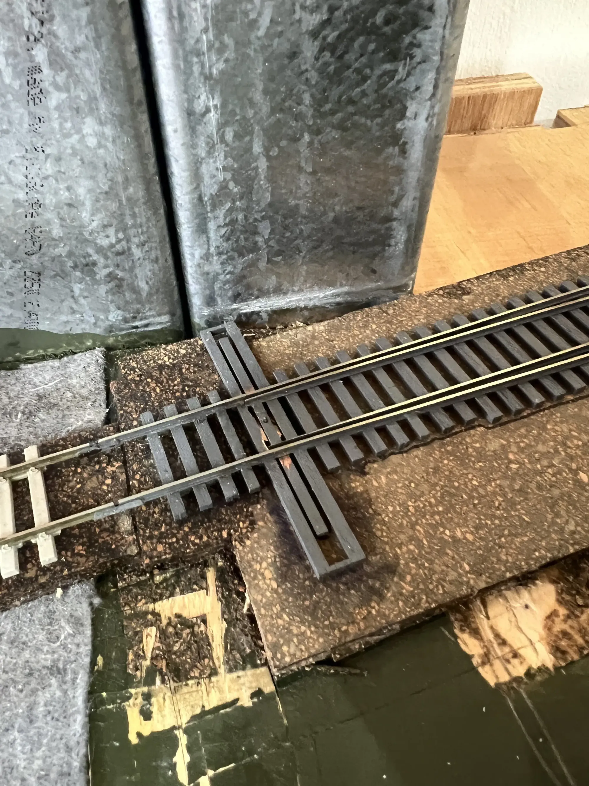
Here's the old board in place. There are 4 block detectors and one servo connected in this section, its at the start of the balloon loop on level 1.
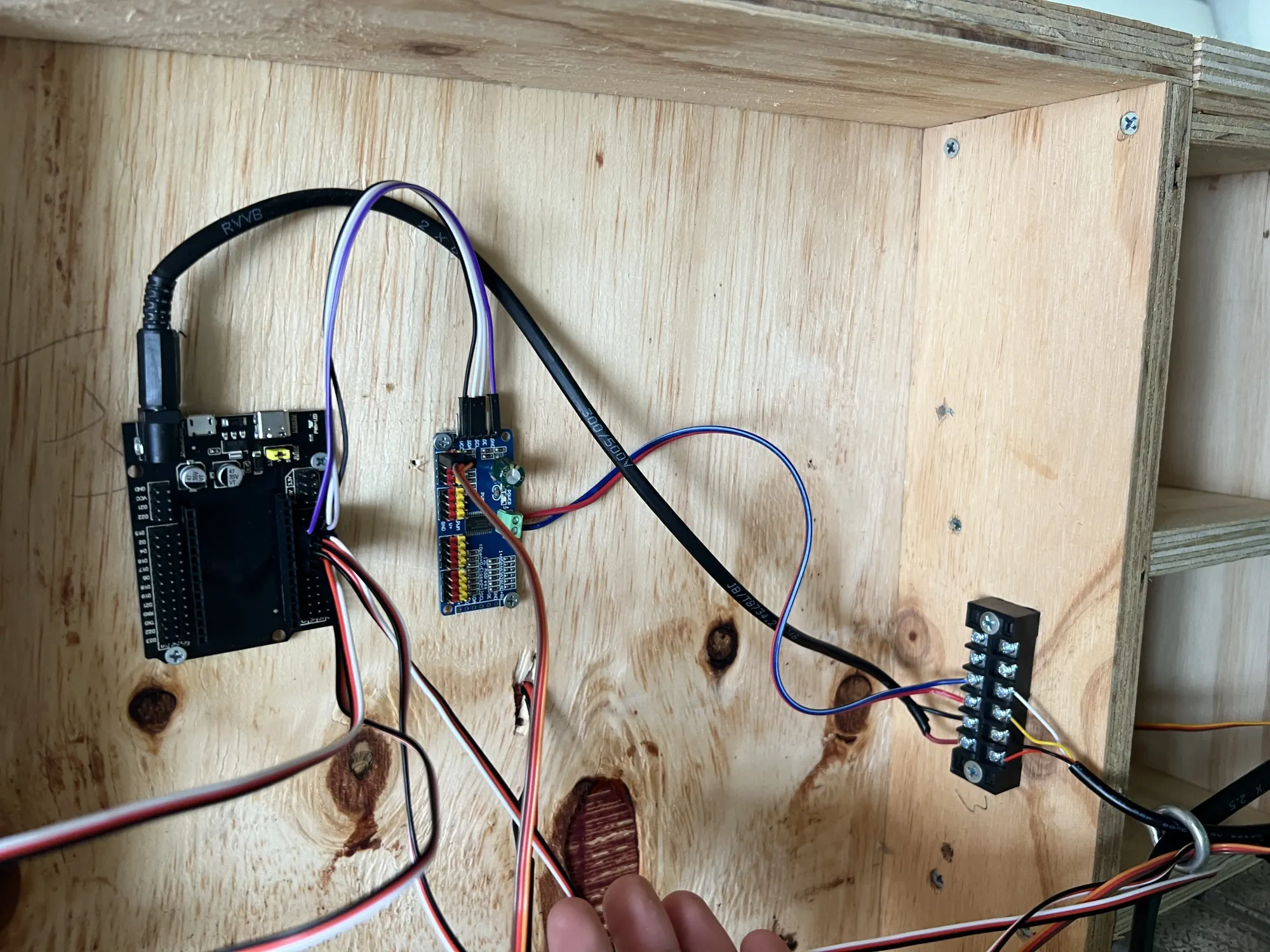
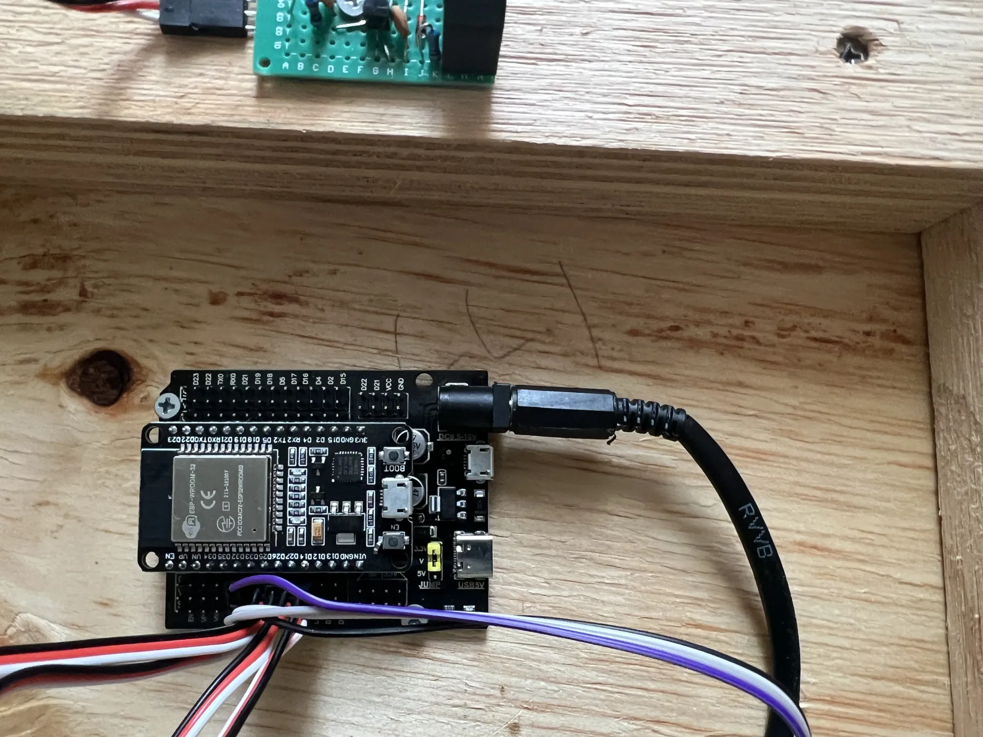
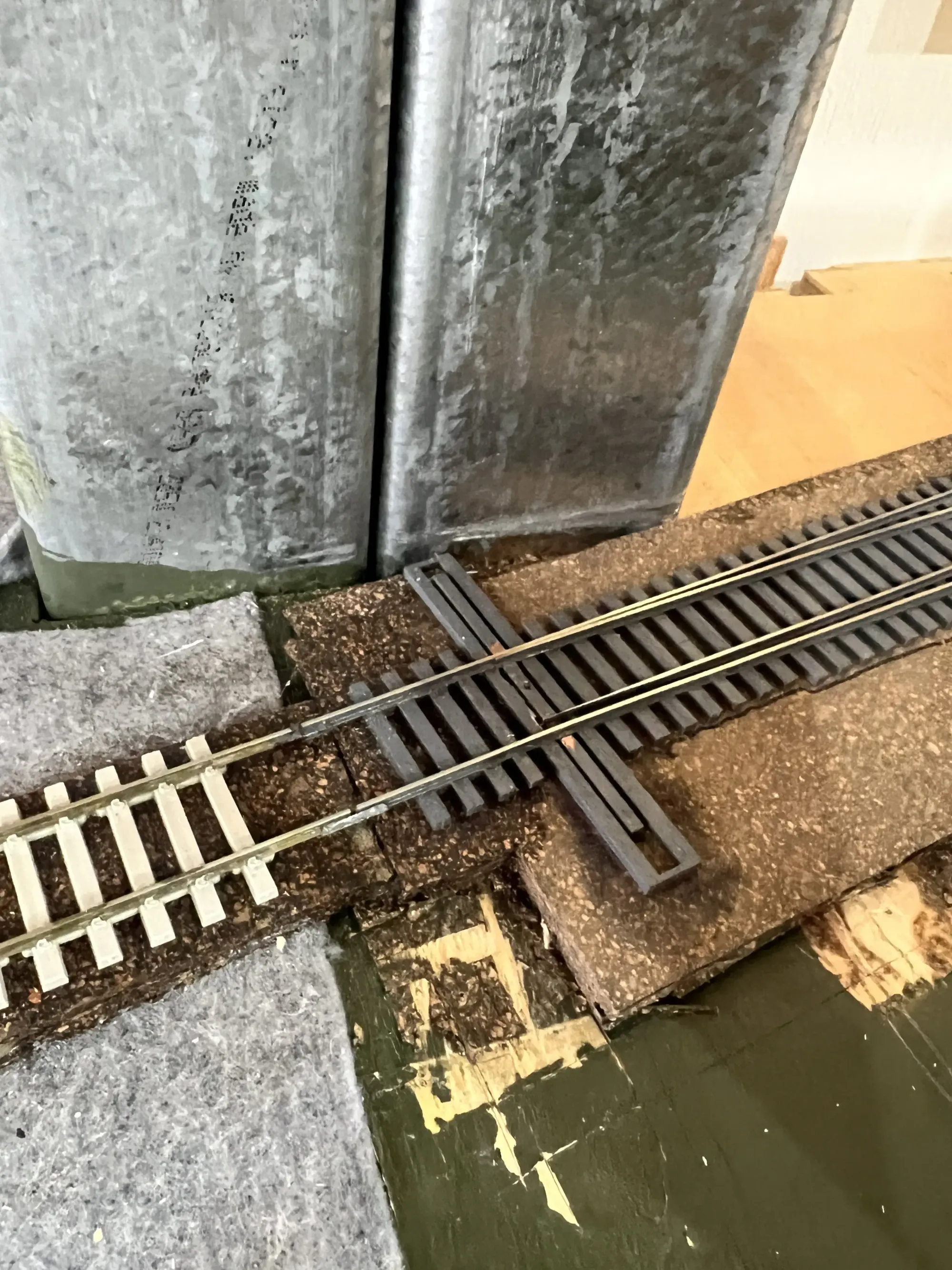
After removing and installing the new board, reconnecting the blocks to the ESP board, and connecting the servo to the PCA - it looks a little something like this:
Bootstrapping the ESP
Now the boards are installed, its time to get the ESP running. Since I had an existing ESP, most of the configuration was there (at least for blocks) but the code needed to be updated to support PCA boards. This was fairly simple, a couple of sections changed from a template I made.
Remove the old ledc output:

Add in the I2C bus, PCA9685 and output blocks:
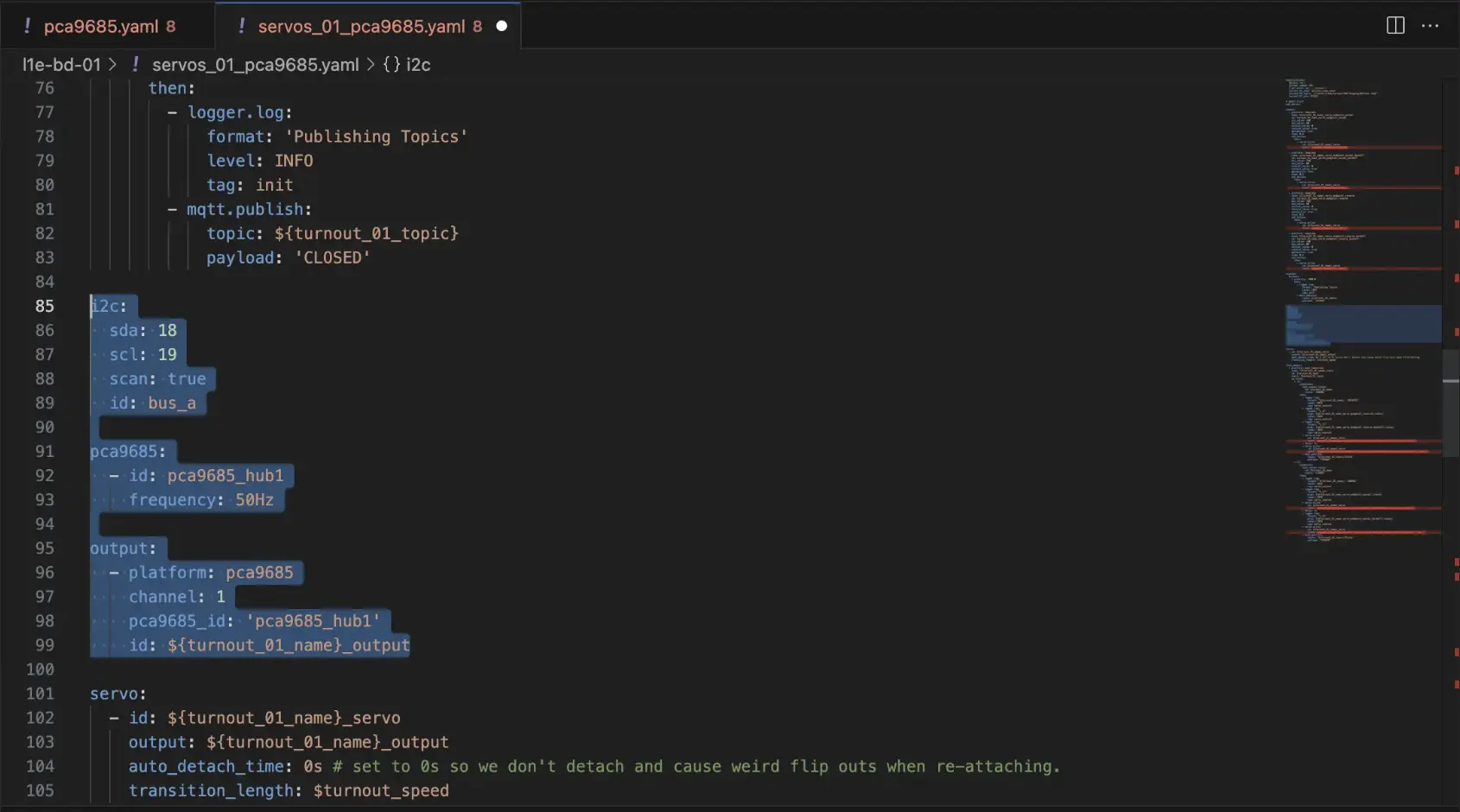
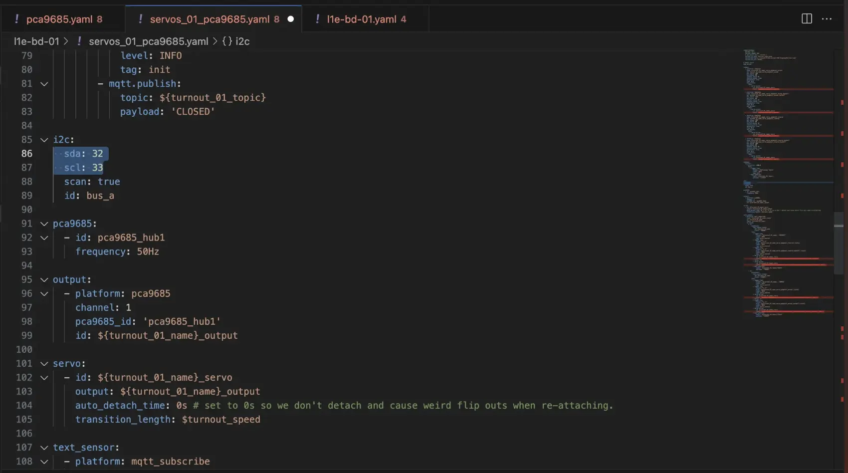
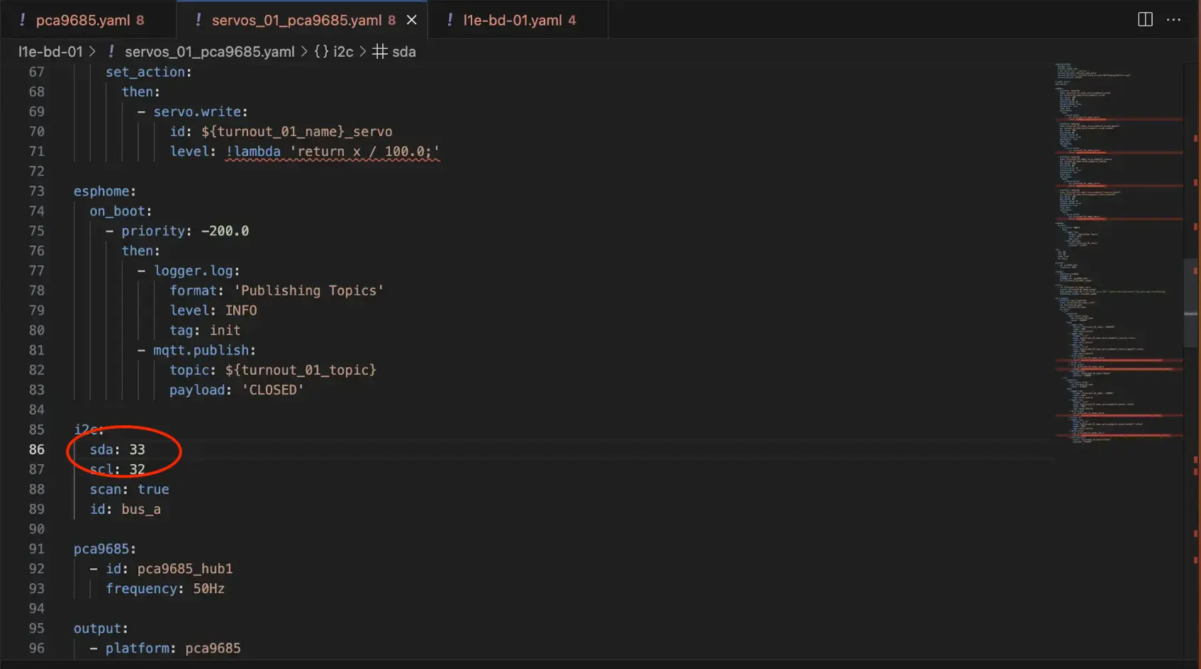
Update the Clock/Data pins based on where the PCA board was plugged into
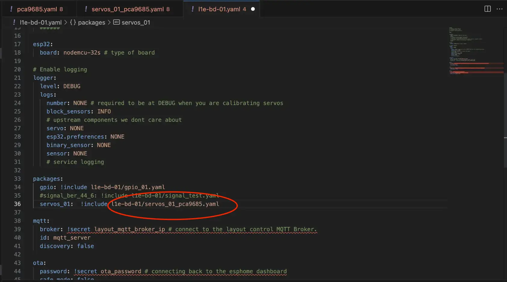
Update the parent YAML with the new file. ESPHome allows you to combine multiple config files for a single device, which is useful to split up blocks/points into their own files and keep each config file small. My structure looks like this:
.
├── kia-bd-01
│   ├── gpio_01.yaml
│   └── servos_01.yaml
├── l1e-bd-01
│   ├── gpio_01.yaml
│   ├── servos_01_pca9685.yaml
│   ├── servos_01_v2.yaml
│   └── signal_test.yaml
├── kia-bd-01.yaml
├── l1e-bd-01.yaml
so the parent YAML files are in the root directory, and each device has its own folder and config files.
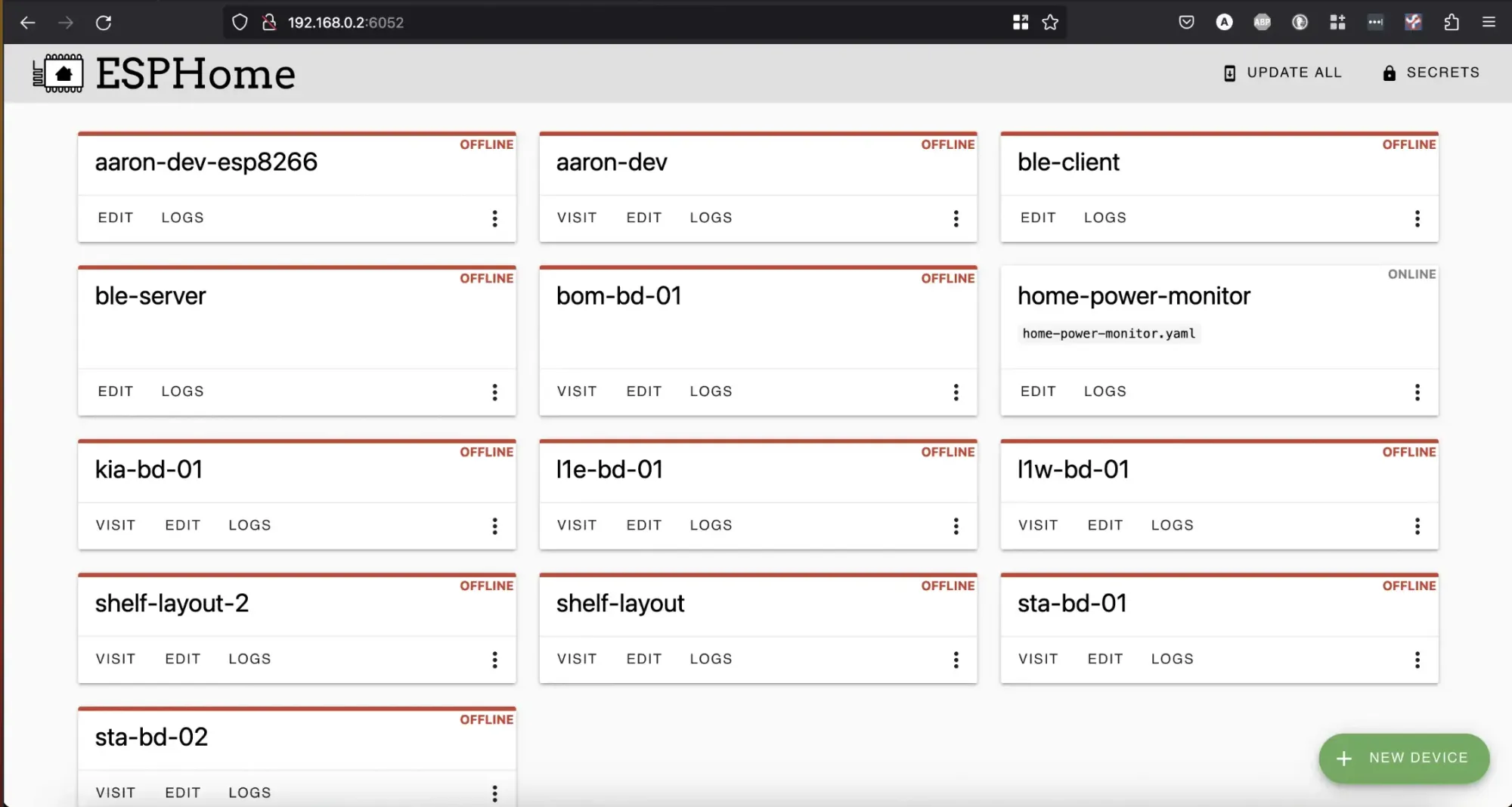
Now the board config is updated, its time to compile the firmware. I use the esphome dashboard in Docker, which provides a nice easy UI to select a board, and create your own firmware:
Clicking Edit on your desired device brings up the parent YAML file. Click install and nominate your method - I chose manual download.

Once downloaded, I use the ESPHome flasher tool to flash directly from my PC, since it has no software on it at present. Once flashed and booted, you see log output in the console.
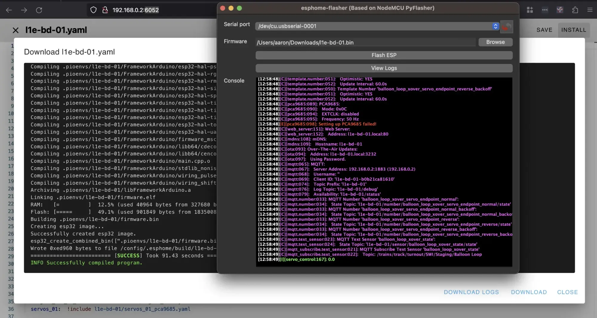
Success! Now it can be installed into the breakout board, and accessed from the ESPHome dashboard:

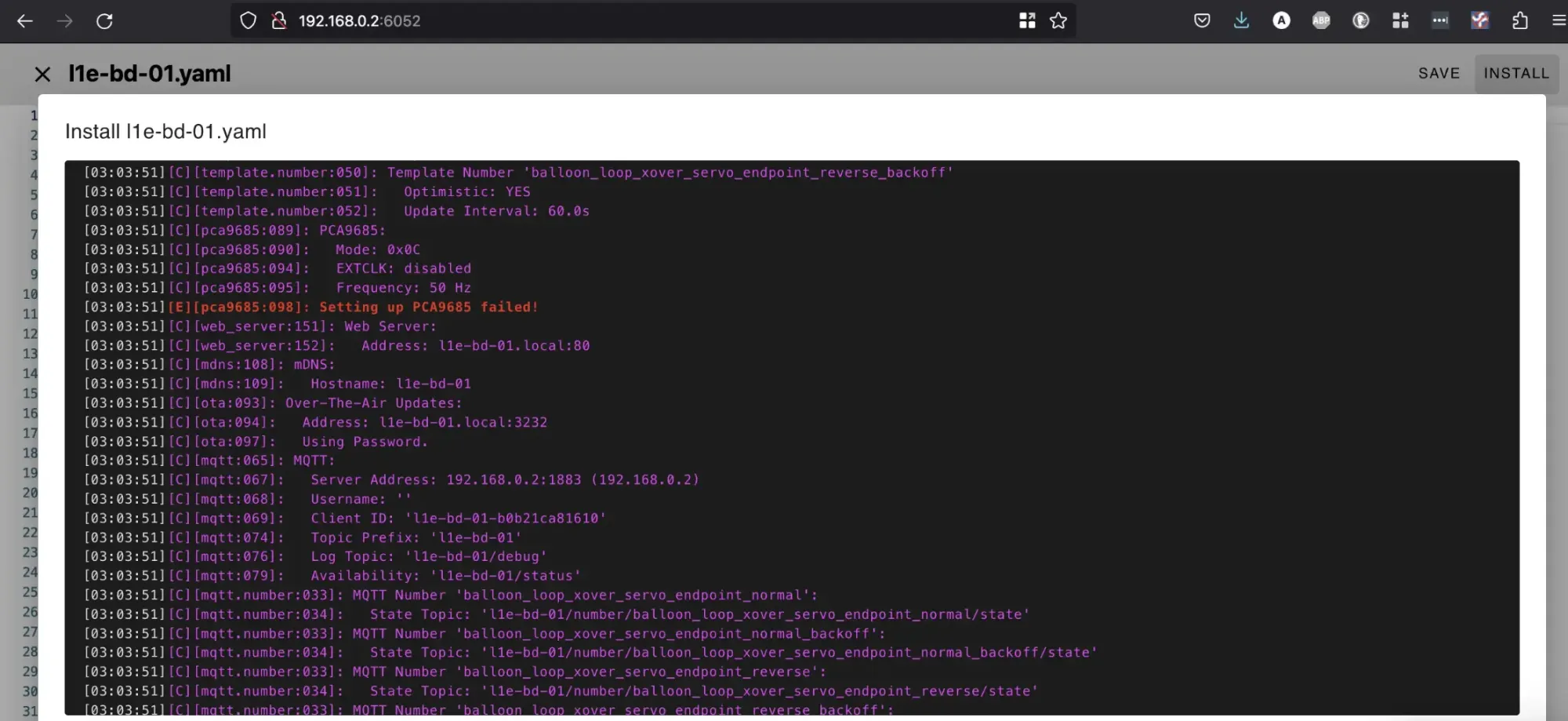
Combing through the logs when it booted, I noticed an error. Hmm, PCA not detected. Quick review of the pins shows I had them backwards - easy fix:
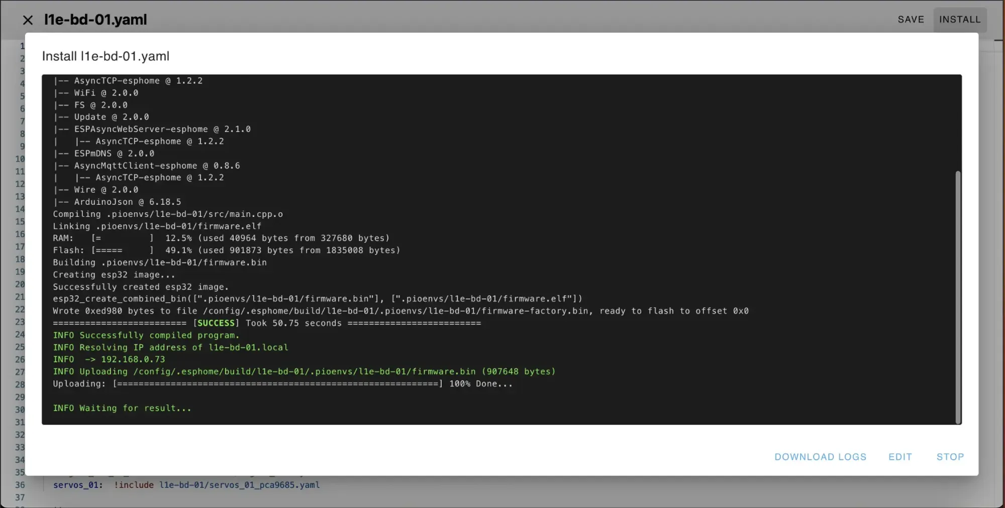
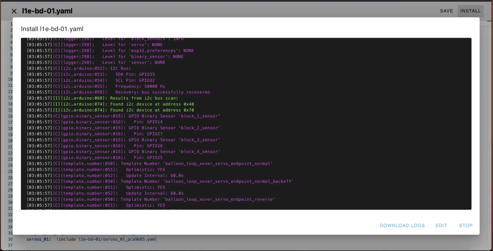
Reflash over wifi, and all green!
Configuring the Device
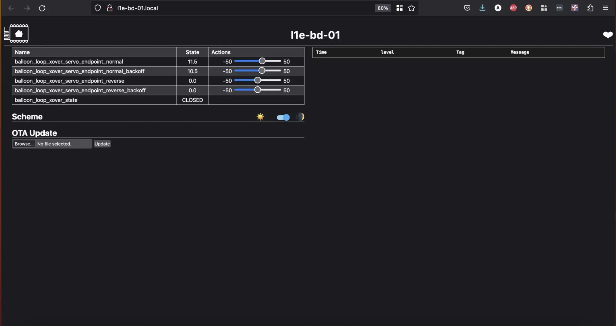
Last step - provisioning the new crossover servo. The ESP has it's own web page, where a couple of config sliders are available to adjust the endpoint of each servo in normal/reverse position. I also have a 'backoff' setting for some crossovers where it take a bit to push them over, and then relax the servo so its not hard up against the rail and persistently buzzing.
As this is designed to be integrated with CATS, it also handles the MQTT topics indicate the point has been thrown at the end of the servo move - which also helps the status remain updated for CATS in the event of a crash.
So we update the normal endpoint:

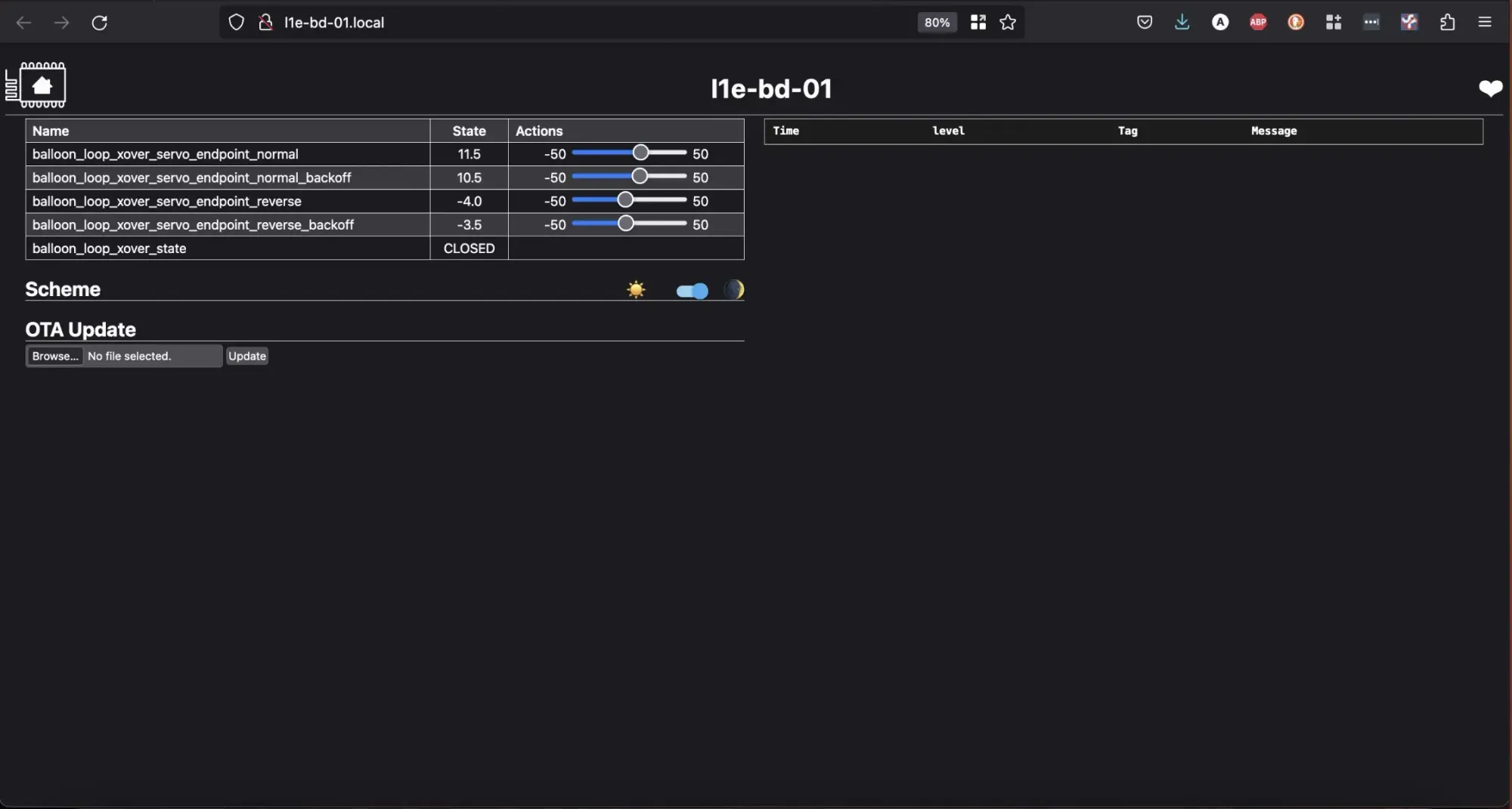
Then the reverse endpoint:
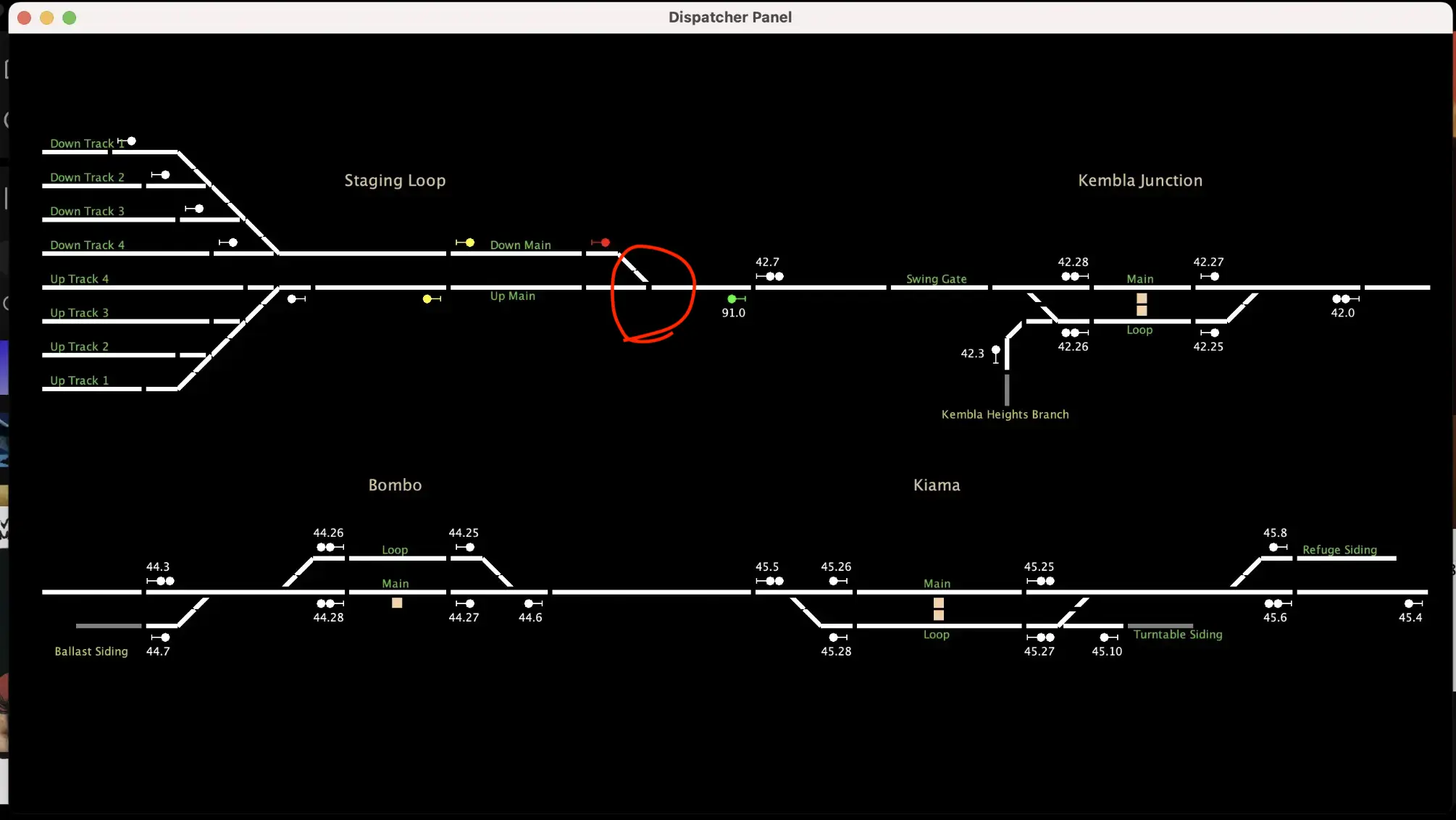
Finally, we launch CATS and make sure everything is all good:
Any updates are reflected in the ESP Logs which helps during troubleshooting:

And thats it! all ready to go. Any updates can be done in realtime over wifi using the sliders. I've got another 5 boards to update, and once I get to the top level I think I'll run the entire yard off one or two ESP/PCA combos - each PCA board supports up to 16 servos.
If you'd like to try this yourself, check out my Repo where i've placed some config file samples, as well as some more info on my block detection https://github.com/aaron9589/esphome-for-model-railroading