Signals for the Illawarra Line
When designing this layout for operations, I really wanted to make an effort in using prototype NSW signalling.
When researching the signals using Driver Route Knowledge Diagrams, I started to realise that some signals will have up to 8-9 lamps per signal. This amount of wiring complicates the install and driving of these signals, so I started looking at ways to overcome this. How can I reduce the wiring required, whilst still giving me all the indications I needed?
Attempt 1
Enter WS2812B. This is a protocol that specific LEDs use to make them addressable and display specific colours. I found some small LED strips on AliExpress and started playing around with the concept of signal heads using these strips. After a bit of playing around, the first iteration of signals eventuated:
Whilst these were promising, they were slightly overscale as the limiting dimension is the distance between LEDs on the strip. I also started looking at route indicators/marker lamps using this method, but I struggled to fit an LED strip across a route indicator.
I built a POC in late 2022 and it kind of went on the back burner shortly after as I turned my attention to building the layout.
Back to the Drawing Board
At some point in 2023 I revisited these signals. For the route indicators and markers, I decided to build my own PCBs and attach SMD LEDs to the board. I used EasyEDA and JLPCB for this, and whilst this looked promising, JLPCB would not assemble the PCBs for me as they didn't meet their minimum size. So whilst the package arrived in the mail, that's about as far as it got. I never got to have the privilege of soldering SMD components!
Another Idea
Another 3 months pass, and I'm watching a YouTube live stream with Seth Neumann and his company Model Railroad Control Systems
One particular product caught my eye - the Simple Signalling System. These are PCB signals with basic colour light indications.
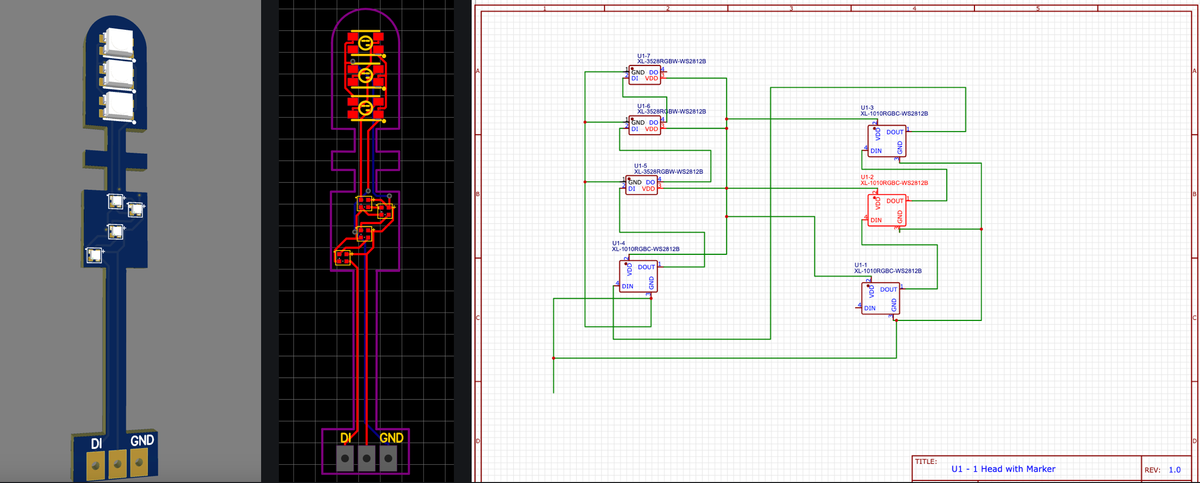
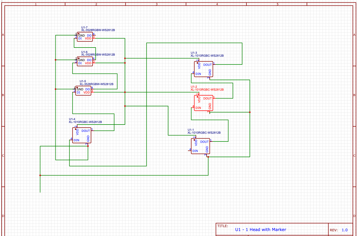
I started to think of combining the addressable LEDs with this approach. A few nights in EasyEDA, and I had built a few prototype signals.
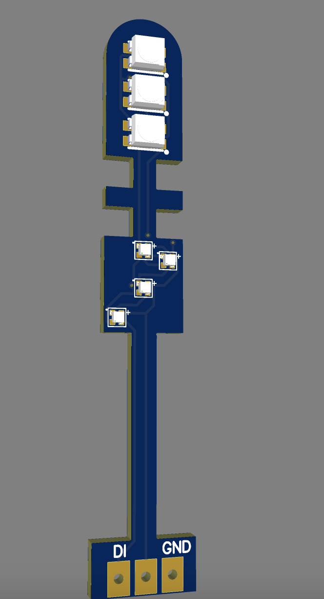
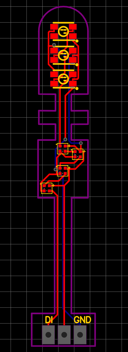
and the best part - because they were above 10mm in size, JLPCB would do the PCB assembly as well!
I mapped out all the signals I needed, what lamps they'd require, etc and used a combination of 1mm and 2mm WS2812 LEDs to contrast the main signal lamp from the others.
Driving the Signals
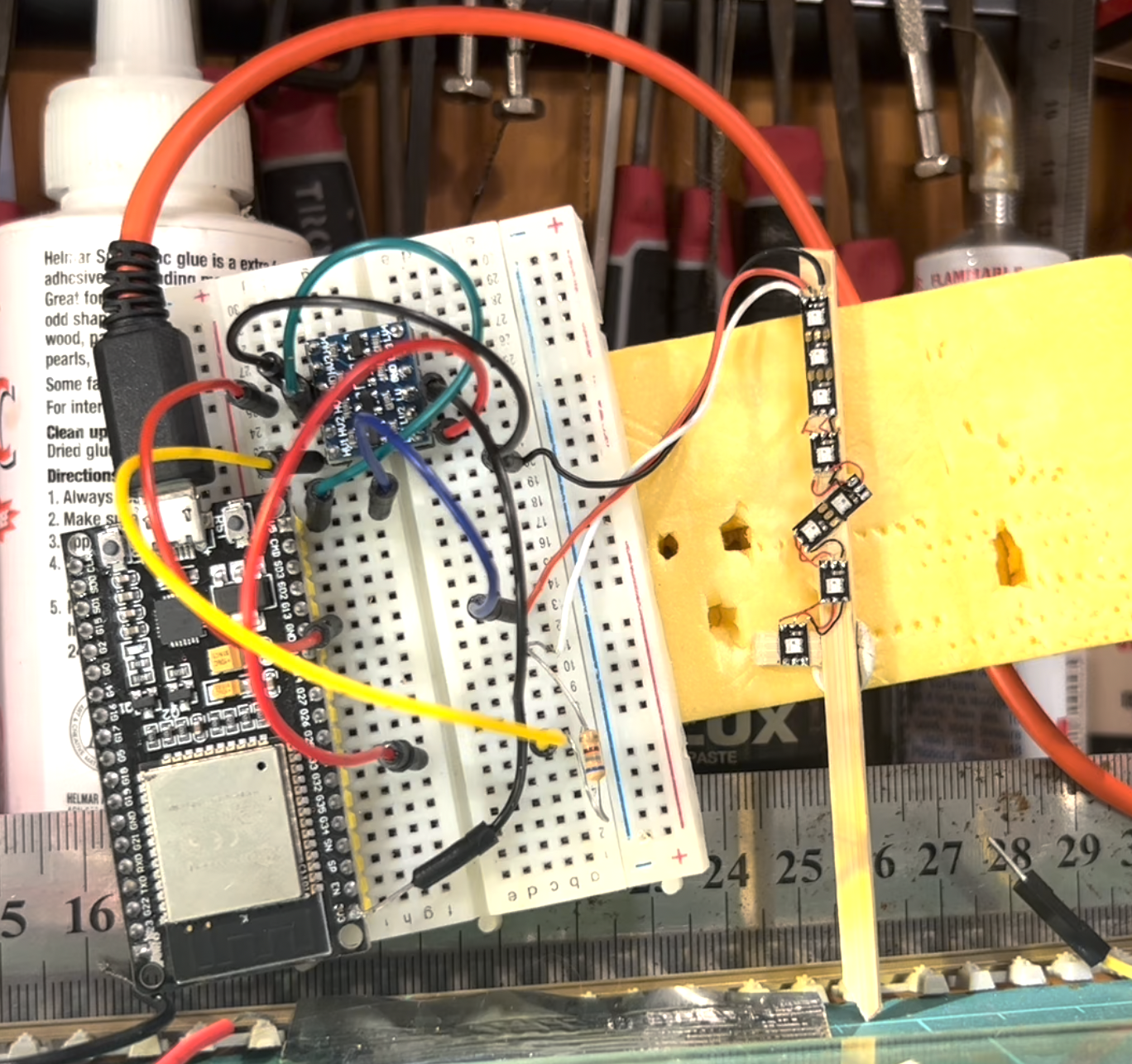
With the creation of the signals underway, my attention turned to how I was going to drive them on the layout. Those of you that have seen my previous posts will see that I am a big fan of ESPHome, which I used for block detection and point motor control.
I started looking at using ESPHome to drive these signals as it does have WS2812 LED support, however I found something as simple as flashing an LED would require some additional code I wasn't keen on writing. That, and I couldn't get a single strip to work with the ESP, so I gave up on that approach.
I soon discovered another ESP-based program called WLED. Whilst its designed for larger strips in rooms and whatnot, I could scale it down for my use case.
WLED supports LED Strips on up to 10 pins, so I could control up to 10 signals per board.
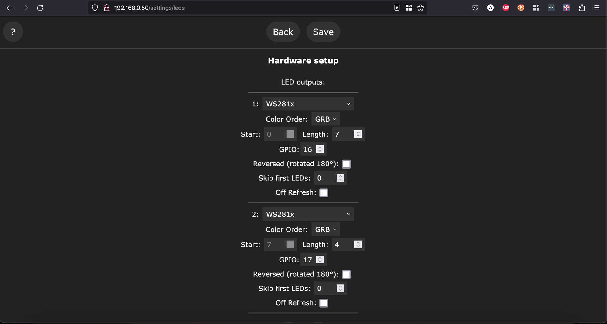
Once I defined the LED pins, I seperate each lamp into a segment. With each segment I can control the colour and effect. So for most segments they are assigned a specific colour, and any yellow LEDs were programmed with an optional blink - I tried to match the timing from a YouTube video of a signal somewhere south of Sydney, I think its pretty close.
Now We're Talking
So with WLED being the preferred choice to drive signals, my attention turned to how I was going to drive this from CATS/JMRI.
Looking at both ends of the communication, this is what I had:
- WLED has a few interfaces, the two I looked at were MQTT and Serial. Both of these interfaces support a JSON API, which allows you to send a state for specific segments of the LED. So each JSON payload ends up being a signal state - approach, stop, proceed etc. These are either sent via MQTT, or via Serial.
- CATS can send specific commands for individual lamps within a signal, or can send a signal indication through Signal Masts.
So to stitch these together, this is what I came up with. In summary:
- Dispatcher changes a signal on the CATS Panel
- The JMRI Signal Mast entry changes state and publishes the new signal aspect via MQTT
- ESPHome listens for specific state changes on these Signal Mask Topics
- ESPHome then passes a message in JSON via serial.

I ended up choosing Serial to remove additional MQTT traffic off the network. Having to go back to the broker and to the WLED device adds additional hops I am trying to avoid - yes its minimal, but its an additional hop back and forth nonetheless.
Configuring the Panel
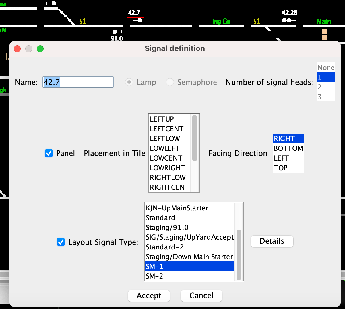
Now we have the plan, lets step through it starting from the panel. First up, I set up the signal on the CATS Panel. All I do here is give it a name - this will match the MQTT mast I create in the table shortly.
The only templates I use are SM-1 and SM-2 - these are stock standard templates with no modifications, the only difference is the number of signal heads (which unlocks additional aspects)
Next I setup the same signal in the masts table in JMRI. I created a custom template based on the names of the aspects that CATS exposed to JMRI, so I could define the mast driver to be MQTT.
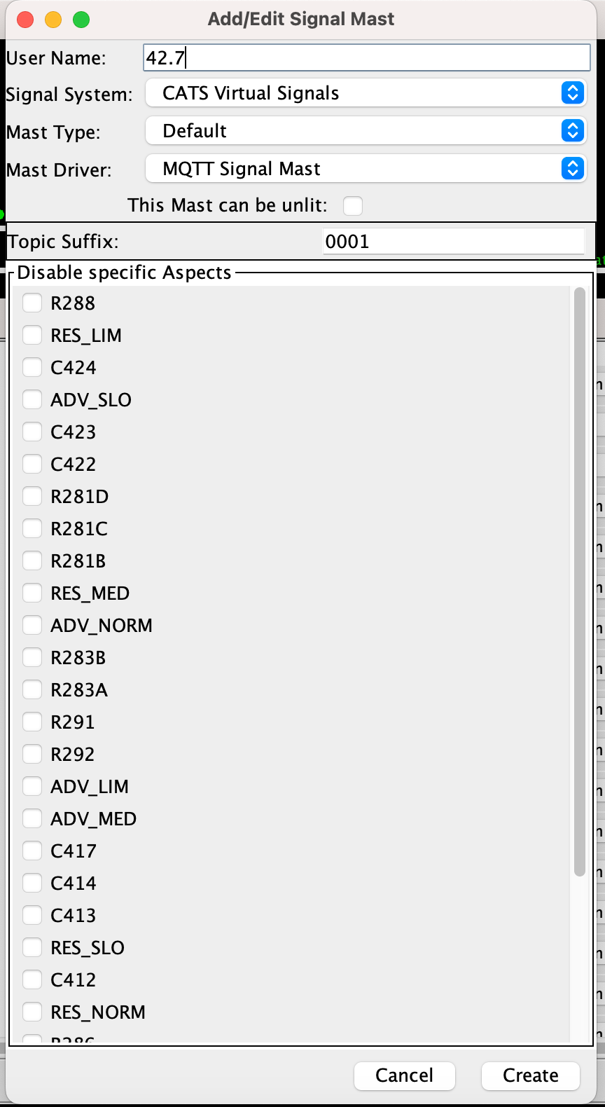
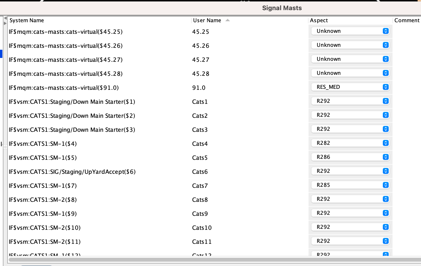
For interests sake, CATS will populate this table with its own virtual signal manager-based signals - but these can't be changed to MQTT as the driver list box is greyed out.
So now if I fire up CATS, I can see when I change the signal, a couple of MQTT messages are published on a topic:
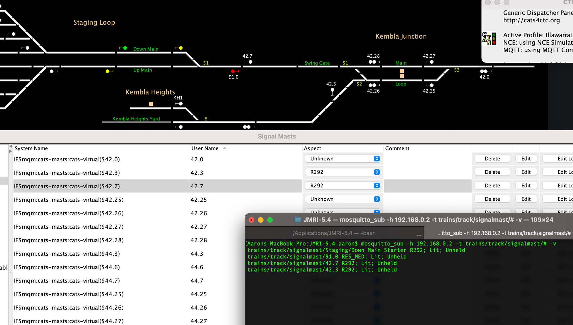
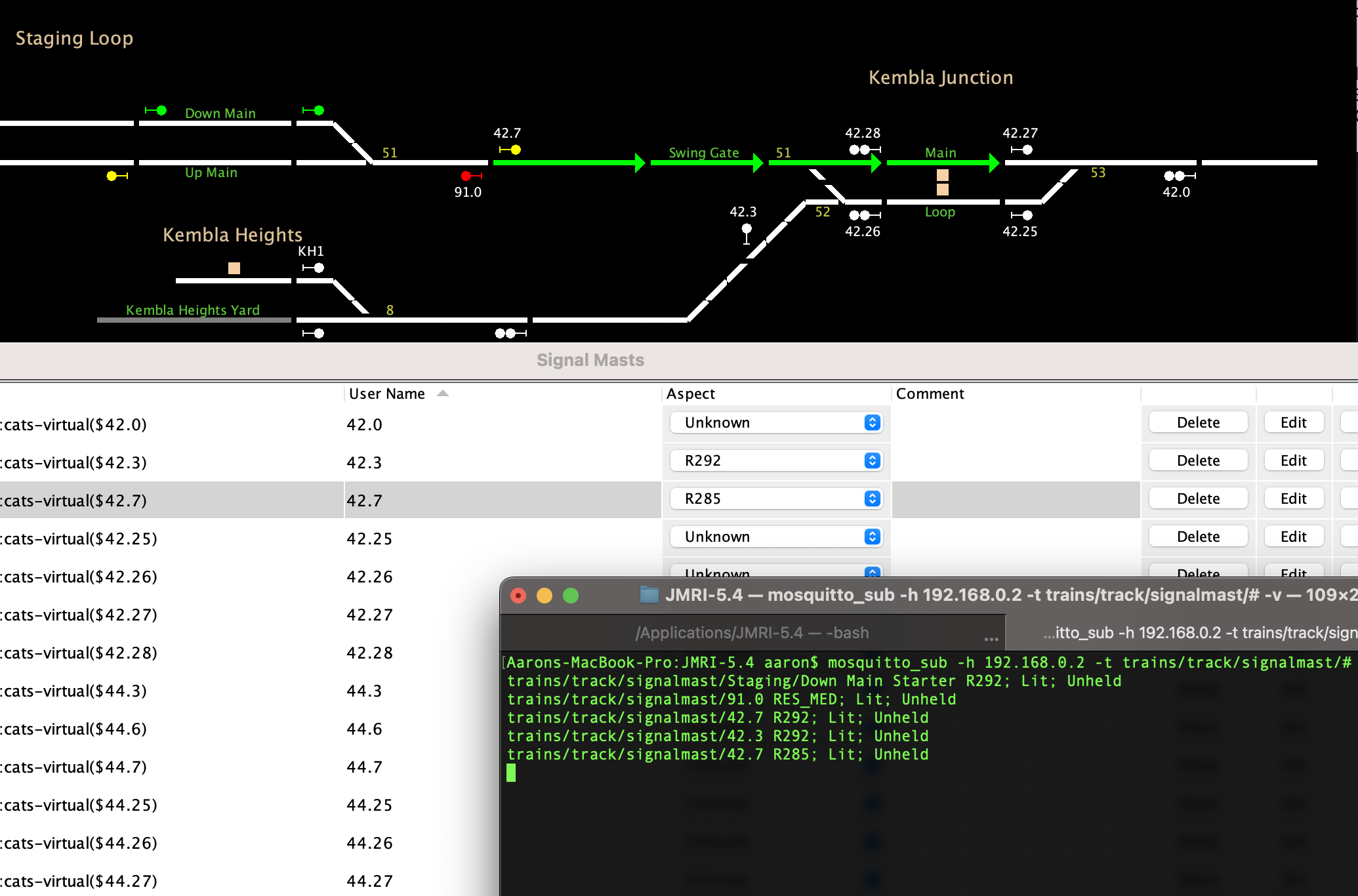
LEFT: Signal at R292/Stop. RIGHT: Signal Displaying R285/Approach
I could match the aspect names to something more familiar, but since I'm setting the aspect in ESPHome, I don't really mind what I get sent in MQTT - as long as its unique for each aspect I need based on the turnouts/condition of blocks ahead.
Now we have a message being sent for each aspect - we need to tell ESPHome what to do with it.
Communicating with WLED
In order for ESPHome to send the message, I need to know the format of what I need to send over the serial connection.
WLED has quite an extensive JSON schema - but all I care about are segments - those things I created earlier through the WLED admin page.
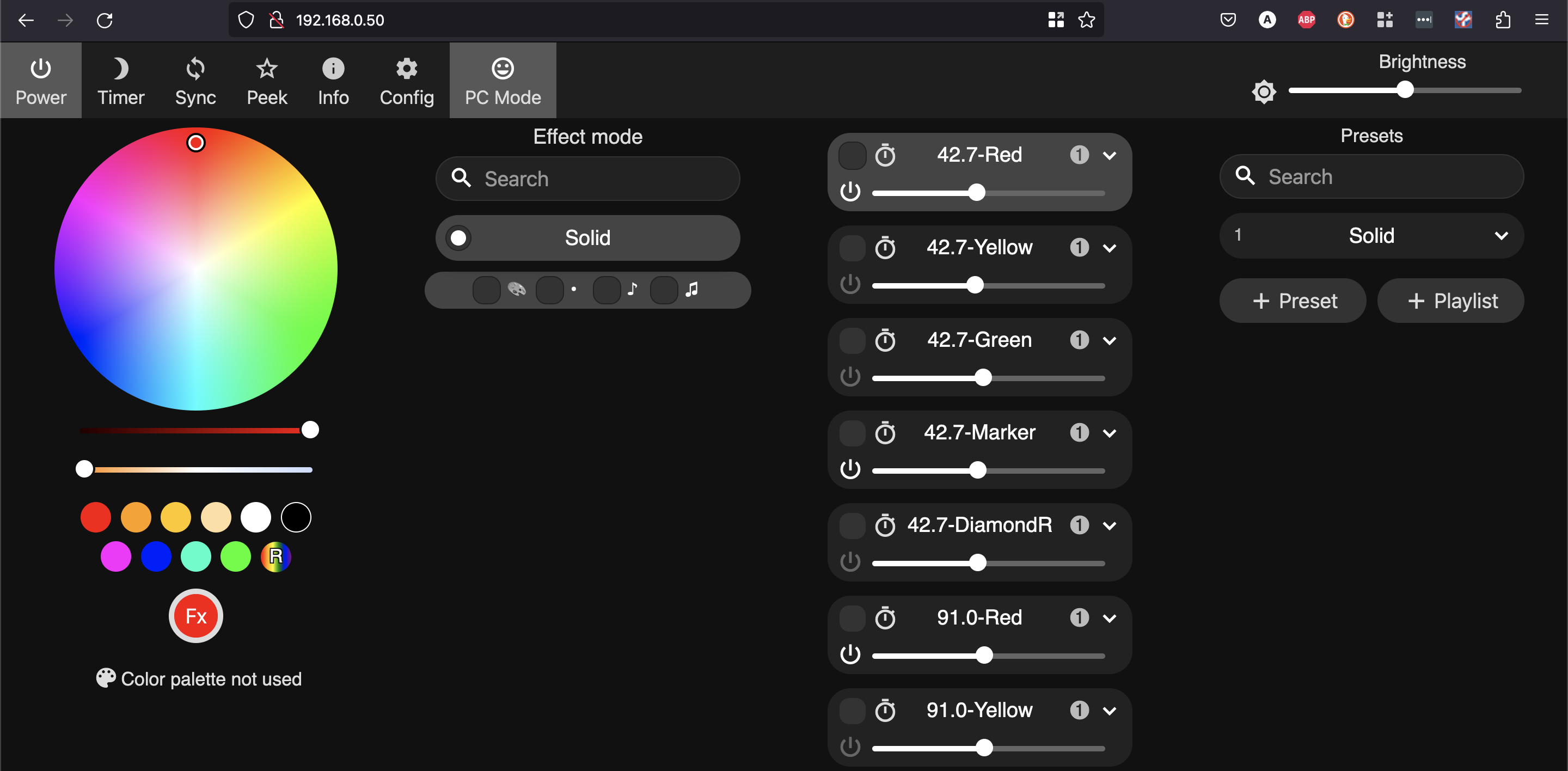
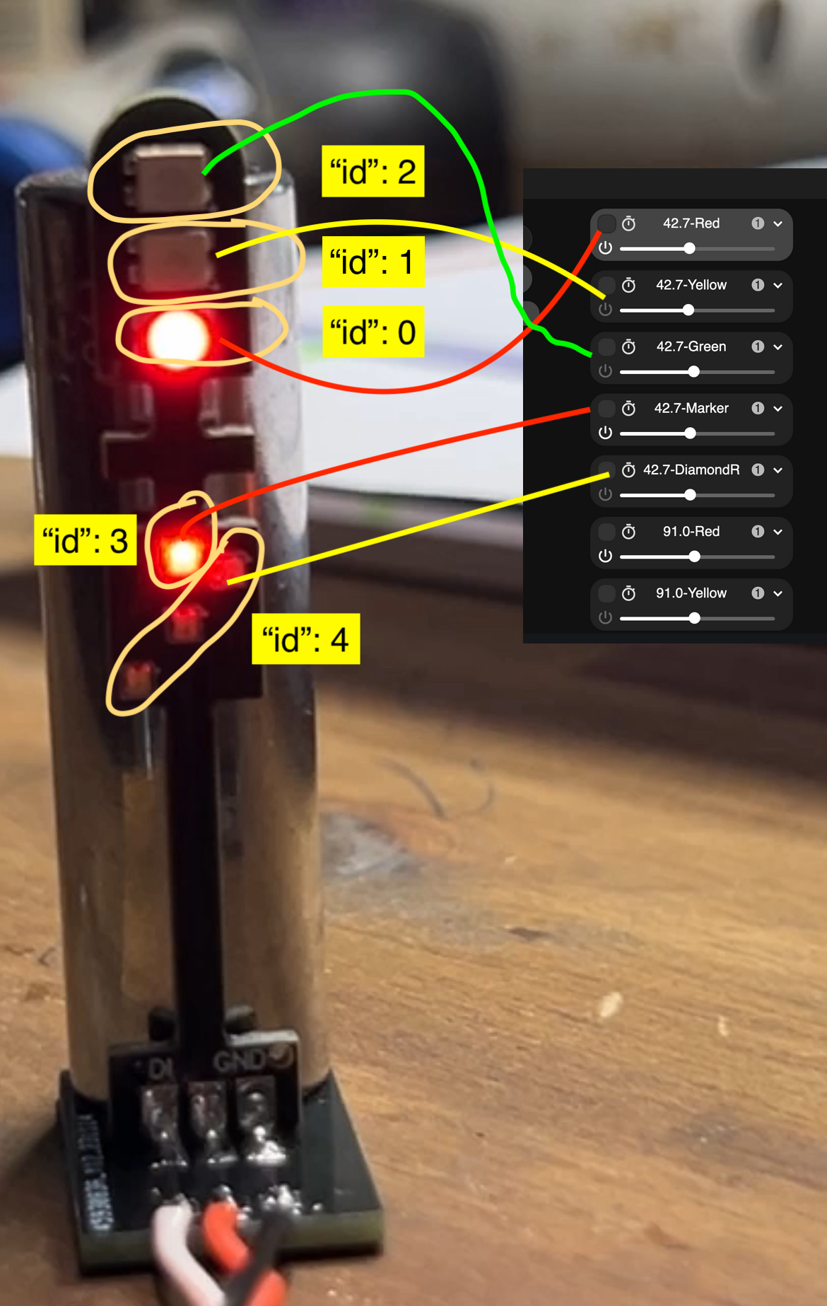
You may recall earlier I set up each individual lamp (or group of lamps for a diamond) into segments. On Signal 42.7, the segments map out in the image below:
Now lets break down one of the JSON strings I use. Adding some formatting makes it a little easier to read.
{
    "seg": [
      { "id": 0, "on": true },
      { "id": 1, "on": false },
      { "id": 2, "on": false },
      { "id": 3, "on": true },
      { "id": 4, "on": false }
    ]
  }
The JSON above represents the stop aspect - note the use of the on property above to turn the LED on. (I've set the colour in the WLED UI earlier).
Segment 4 is the route diamond, which has 3 LEDs in its segment as opposed to 1.
Each of the segments have their colour set through the WLED admin page, and for the yellow aspects the flash rate is defined. Anytime I want to flash, I add an additional attribute of fx - setting this to one triggers the 'blink' effect.
{ "id": 4, "on": true, "fx": 1 }
Could I have arranged the segments better? Probably.
Will I come up with a standard 6 months from now and re-work everything? You bet.
Configuring ESPHome
So a bit more of an understanding of WLED, lets see how we can integrate this with ESPHome.
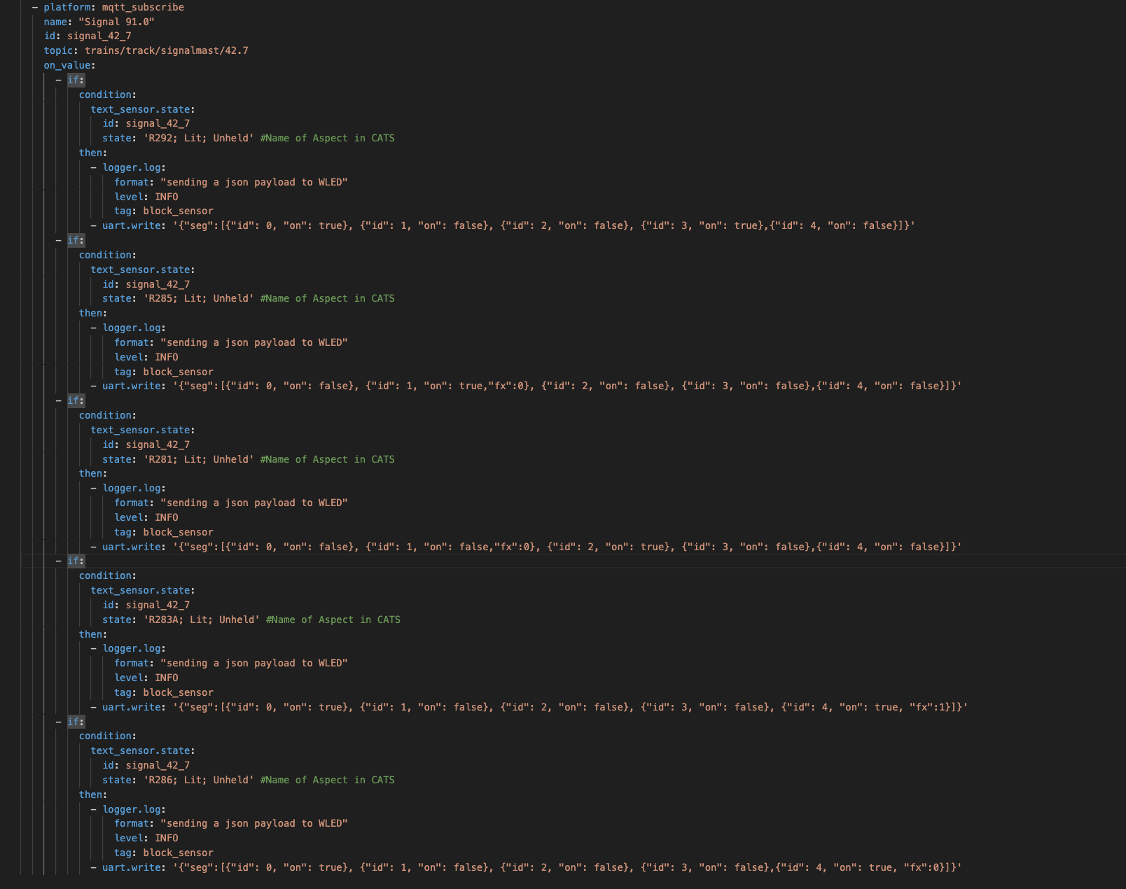
I have a bunch of MQTT Text Sensors, and based on what JMRI sends from the signal mast table, we send a JSON payload over serial (uart.write) to change the individual lamps and if needed, their effect (to flash/not flash).
---
logger:
  baud_rate: 0

uart:
  tx_pin: 1
  rx_pin: 3
  baud_rate: 115200

text_sensor:
  - platform: mqtt_subscribe
    name: "Signal 91.0"
    id: signal_42_7
    topic: trains/track/signalmast/42.7
    on_value:
      - if:
          condition:
            text_sensor.state:
              id: signal_42_7
              state: 'R292; Lit; Unheld' #Name of Aspect in CATS
          then:
            - logger.log:
                format: "sending a json payload to WLED"
                level: INFO
                tag: block_sensor
            - uart.write: '{"seg":[{"id": 0, "on": true}, {"id": 1, "on": false}, {"id": 2, "on": false}, {"id": 3, "on": true},{"id": 4, "on": false}]}'
You can see that we setup a sensor based on the MQTT Topic trains/track/signalmast/42.7 - and then if the payload equals R292; Lit; Unheld, send the JSON payload for Stop using uart.write over the Serial Interface.
This logic is repeated for each aspect. Set the route in CATS, record down the value of the signal mast, set the JSON payload to match the desired aspect, and add it to the YAML:
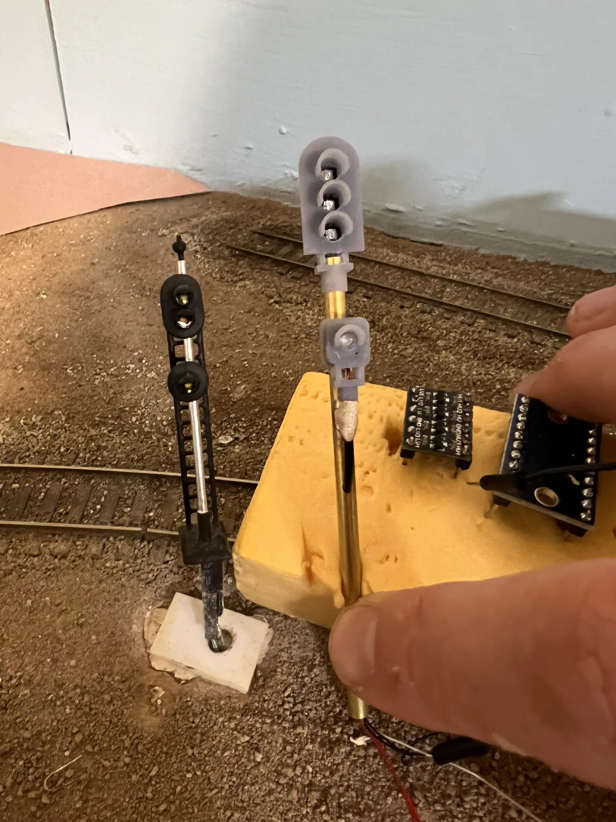
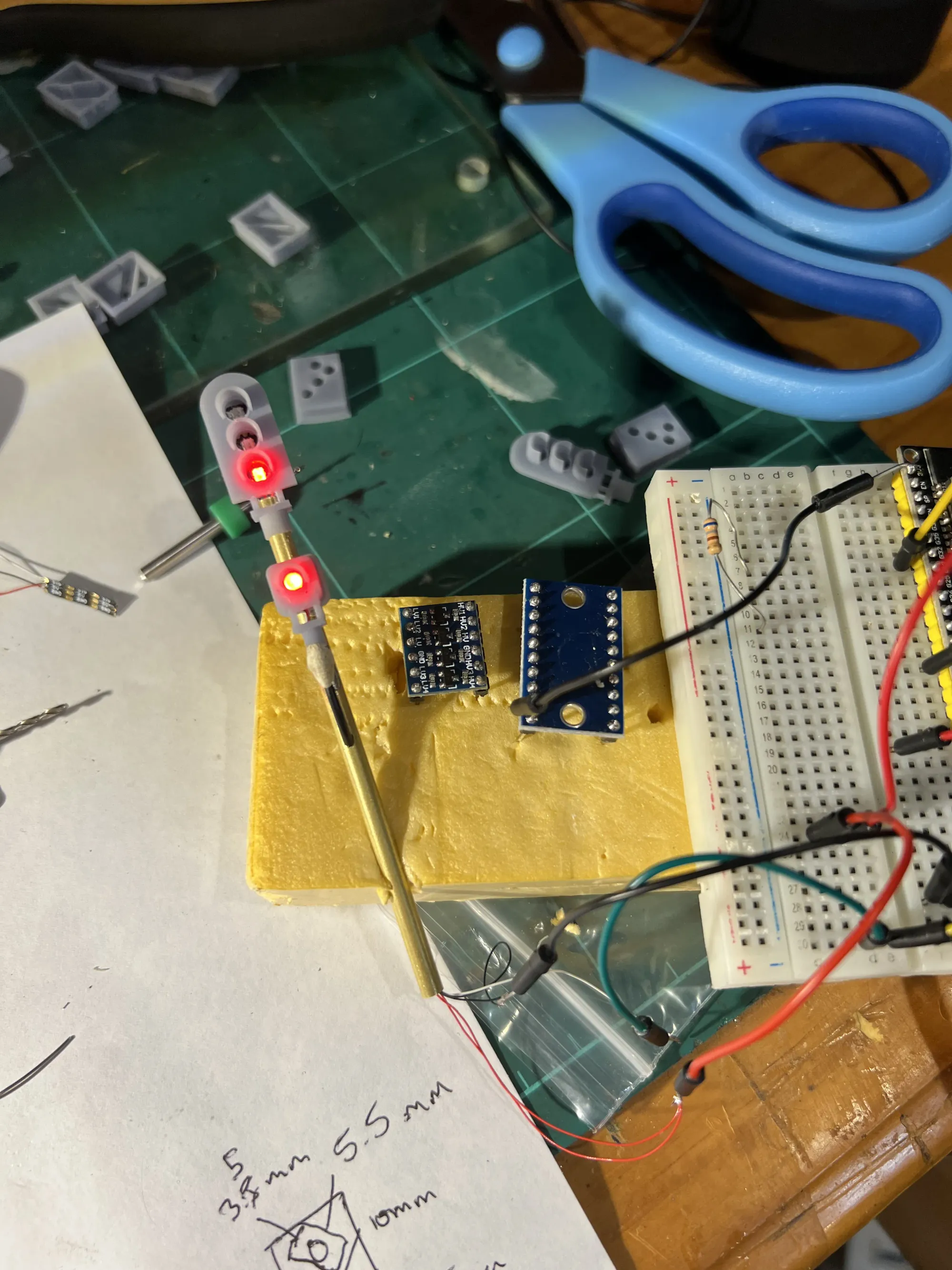
The Finished Product
Once the signals arrived, it didn't take long for them to end up on the layout. I'm really pleased with how they've turned out. Whilst they don't look like a traditional signal, the fact they can display prototypical aspects offsets it enough for me. I'm hoping to revisit the signals one day and encase them in a 3D print enclosure, but for now this gives me something to drop on the layout, and use when I start operating in the not too distant future.
Sharing the Knowledge
For those that are interested, I am planning on publishing these PCBs on GitHub once I've ordered a few variants and ensured they all work, so you'll be able to download and fabricate some of your own. If you need additional specific designs, feel free to take these and add your own variants so we can build up a collection of designs in the repo: https://github.com/aaron9589/nsw-railway-pcb-signals